Baubeschreibung MD-11
Building an MD-11
Daraus wird eine MD-11
entstehen:
That’s what you need to build an MD-11:
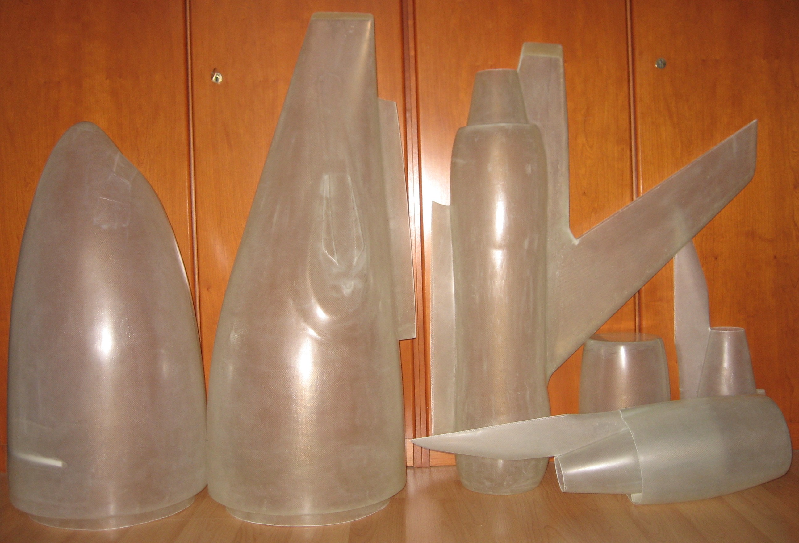
Der GfK-Teilesatz aus
eigenen Formen
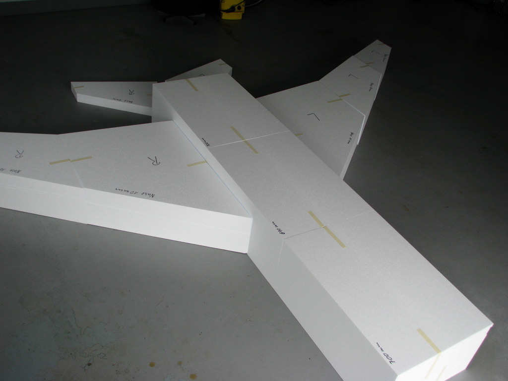
Fertig geschnittene Styroporkerne von Manfred
A set of fiberglass parts from my own molds Ready-cut
styrofoam cores from Manfred
Der Bau beginnt
Let’s start the build
Teil 1: Rumpfheck
Part 1: Tail section
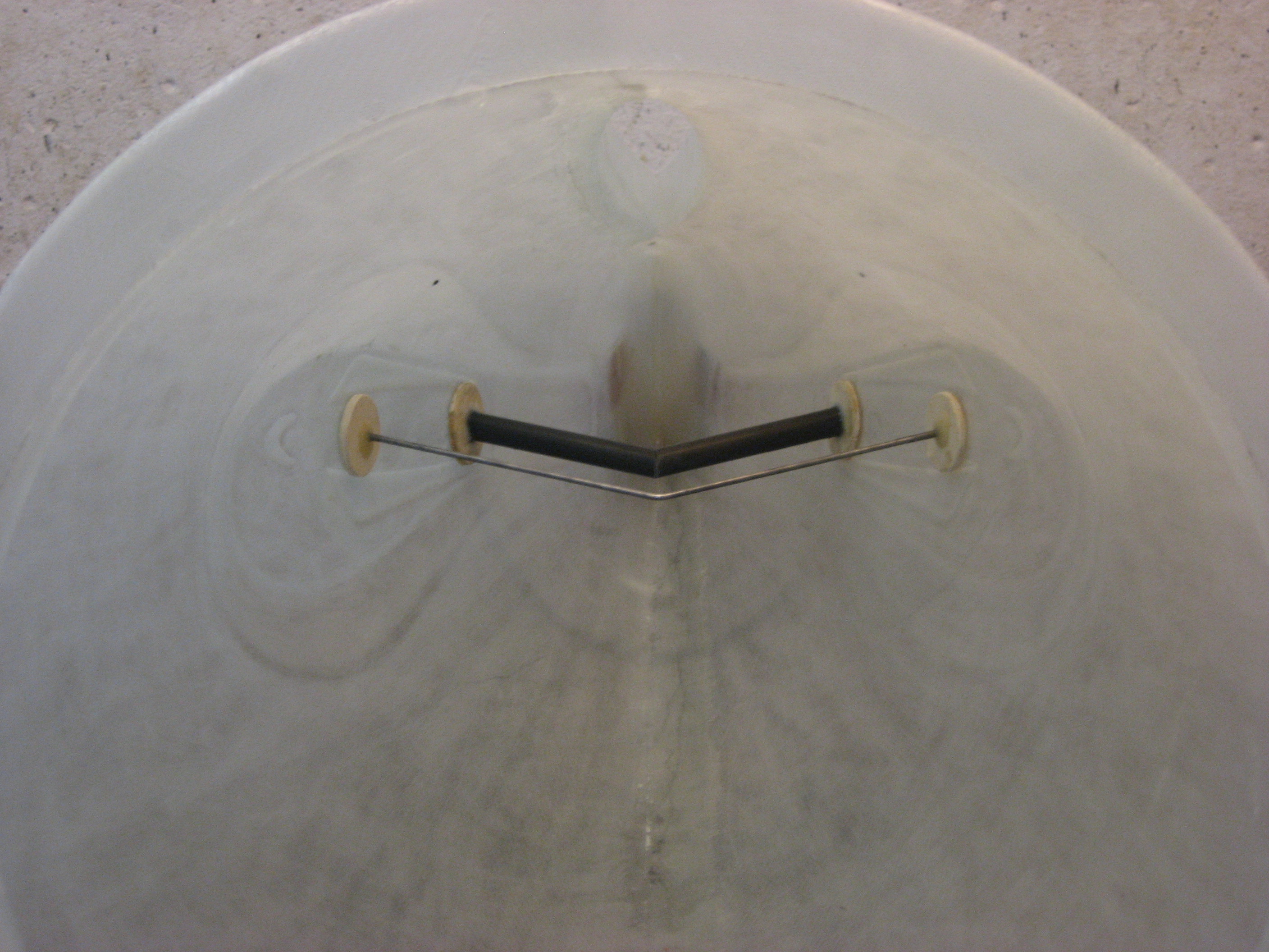
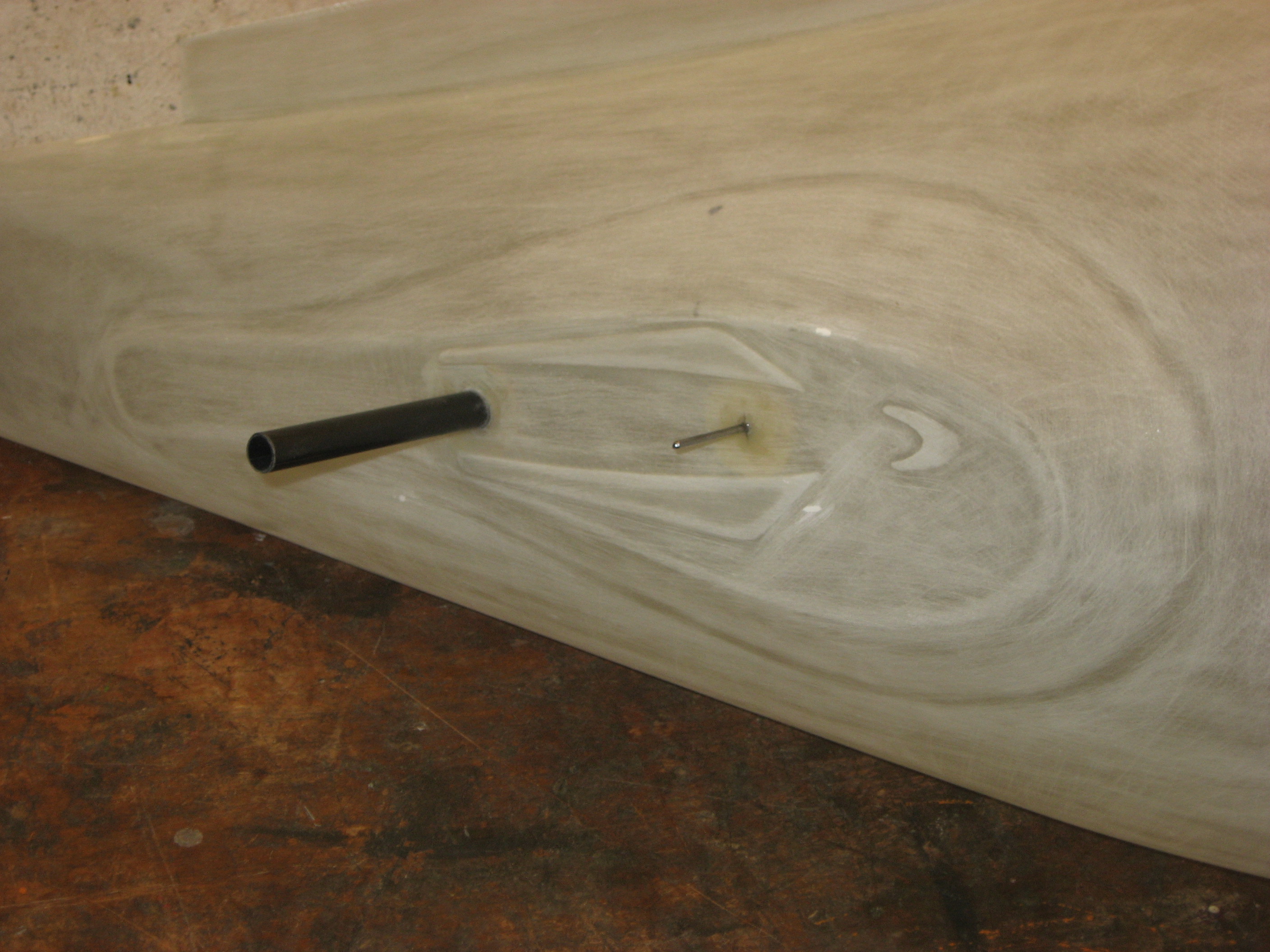
Steckungsrohre für das
Höhenleitwerk im Rumpfheck verklebt
Horizontal stabilizer tubes glued into to tail cone
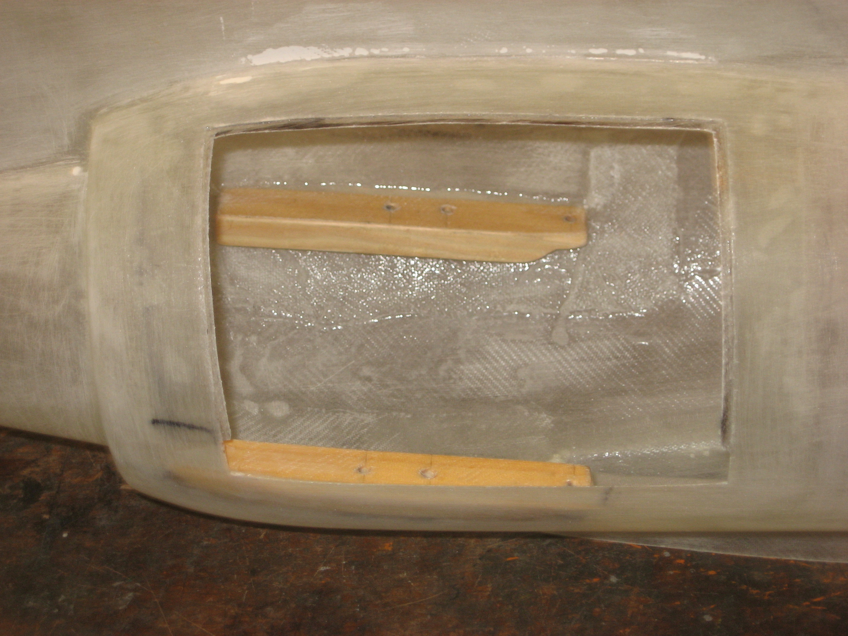
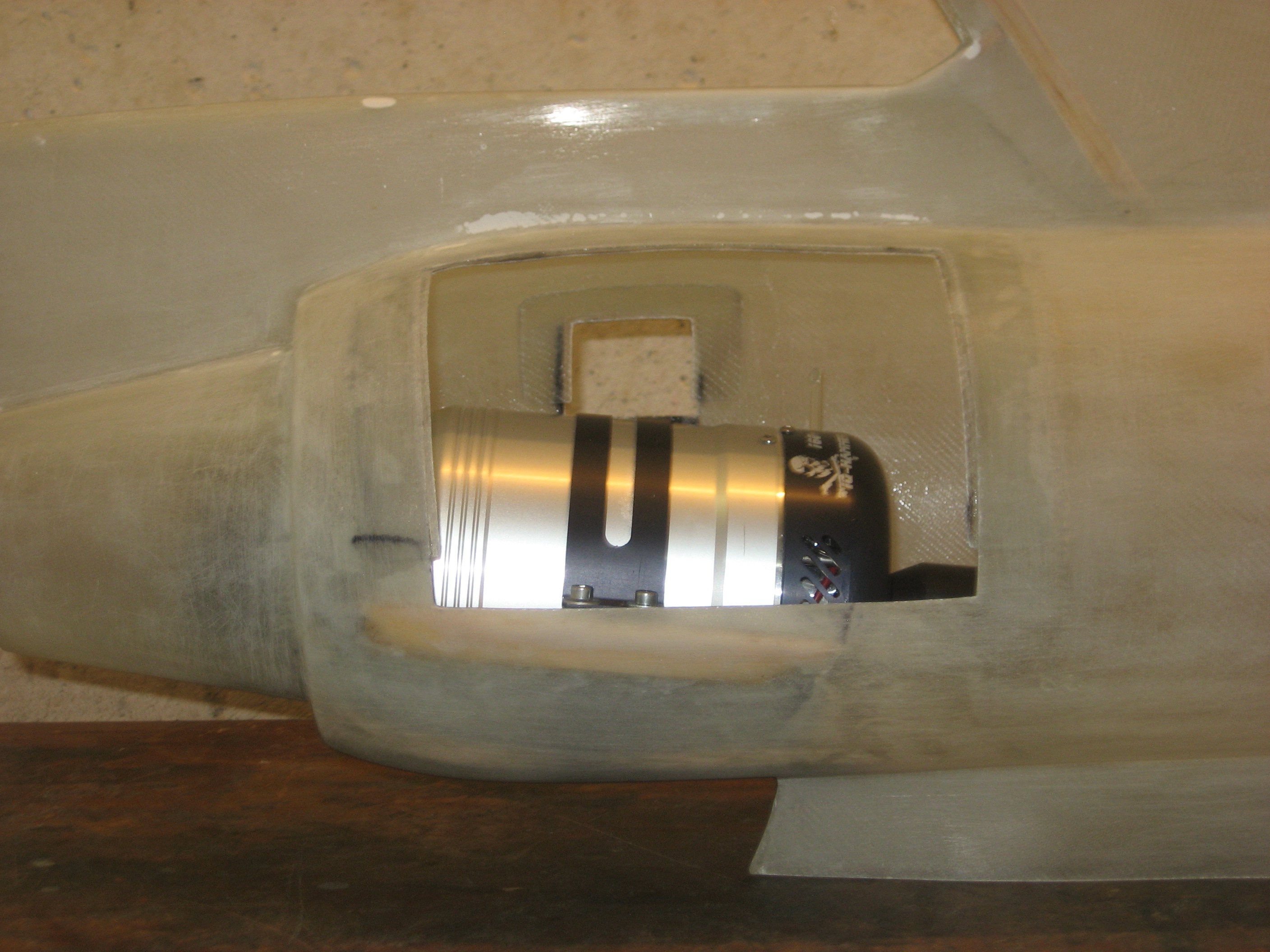
Einbau der 160er Turbine mit
6 Grad Anstellung
Mounting for the 36 lbs. turbine with 6 degrees of incidence
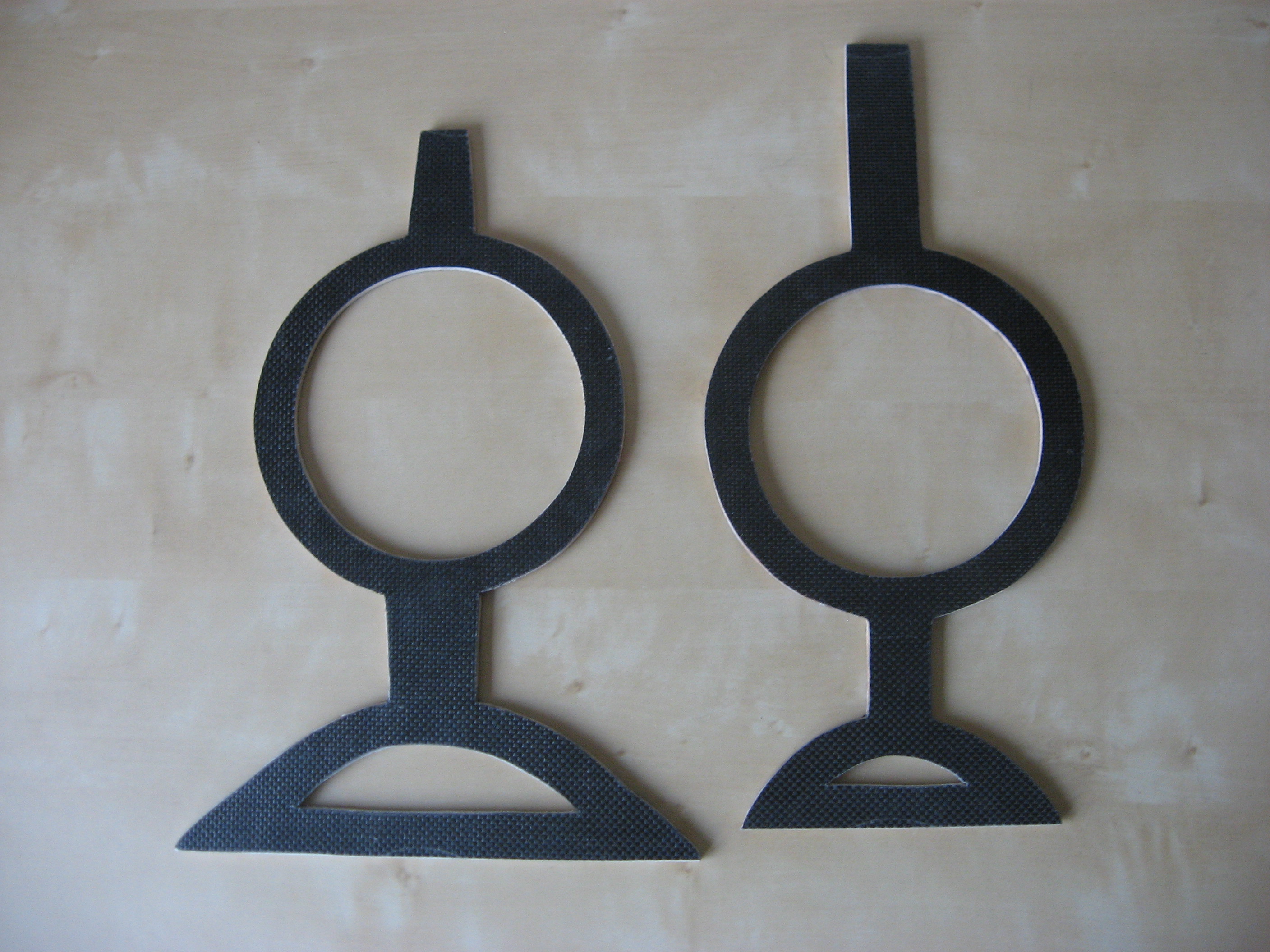
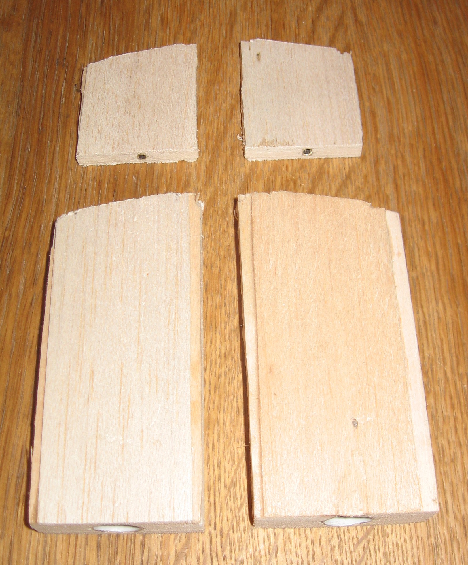
Kohlefaser-Balsa-Spanten stabilisieren
Seitenleitwerk und Hecktriebwerk
Carbon-balsa formers provide stiffness for fin and tail nacelle
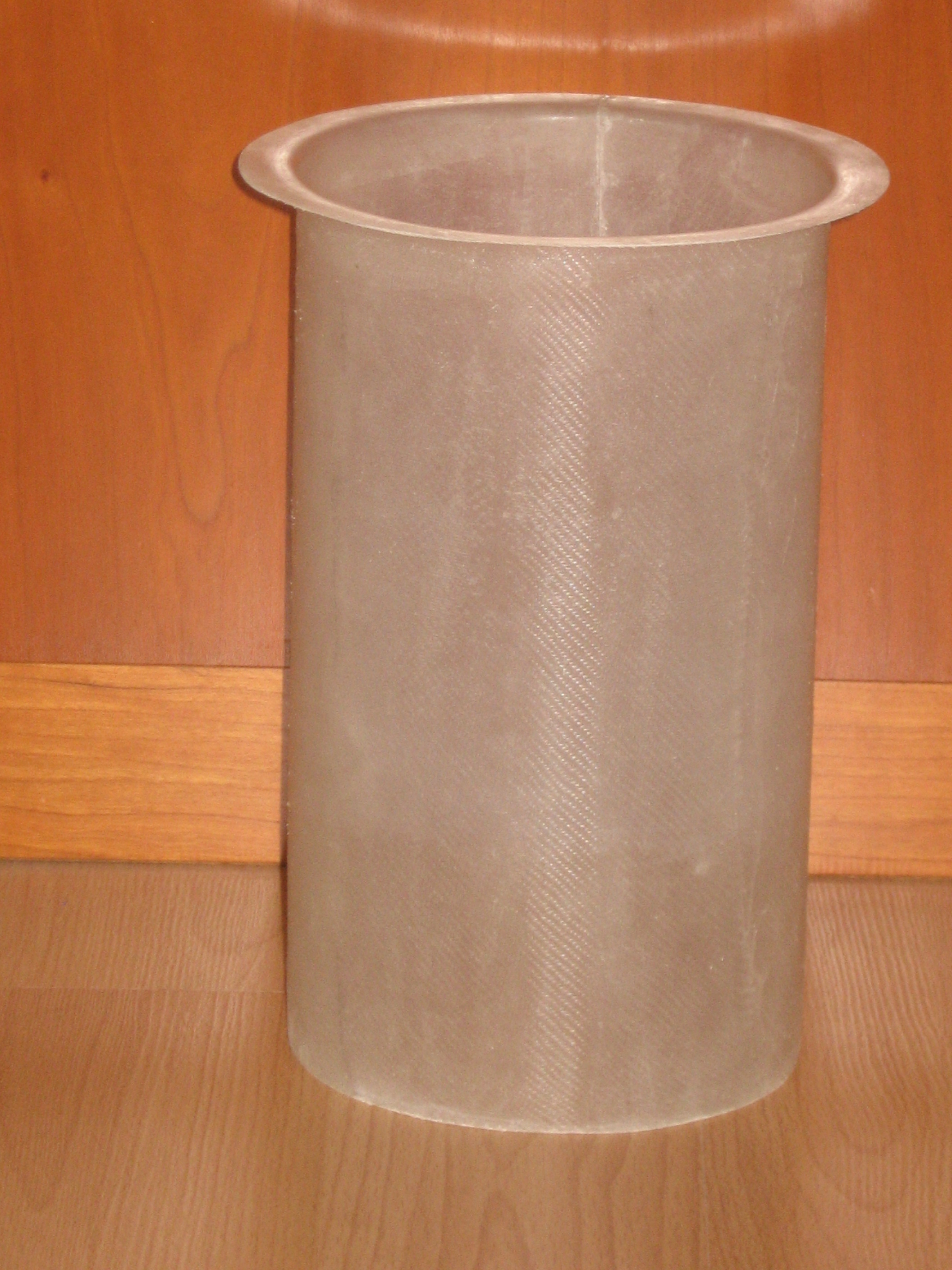
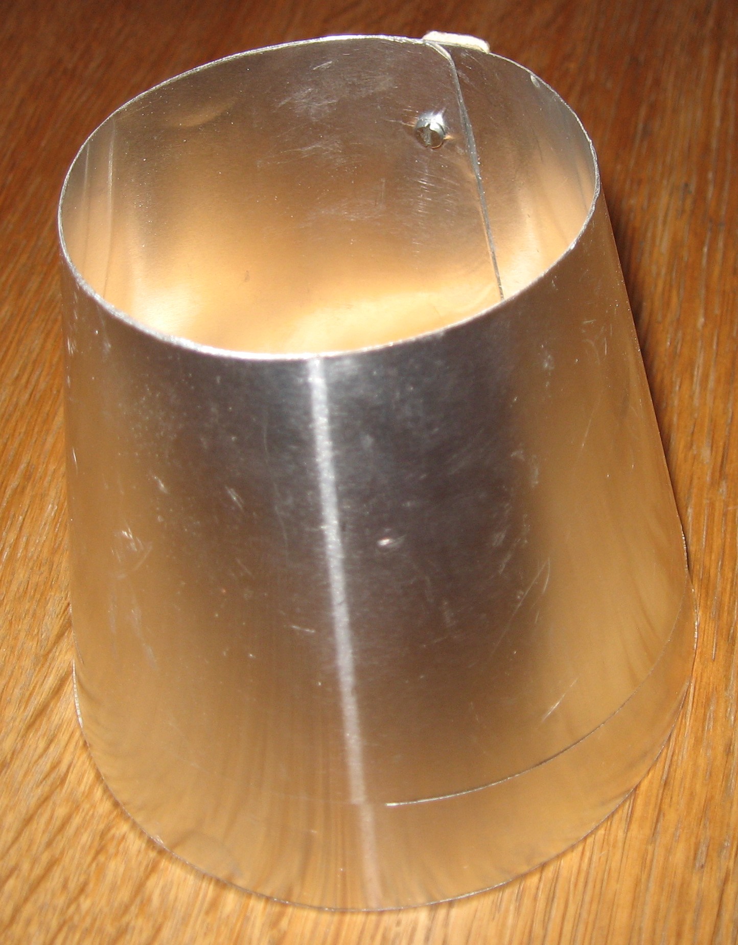
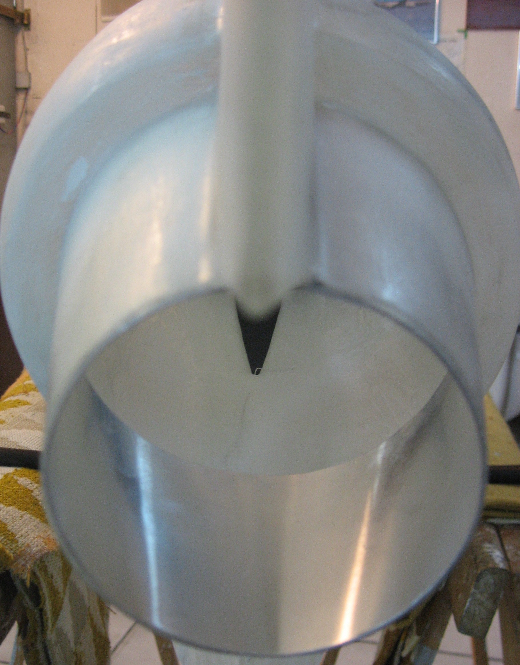
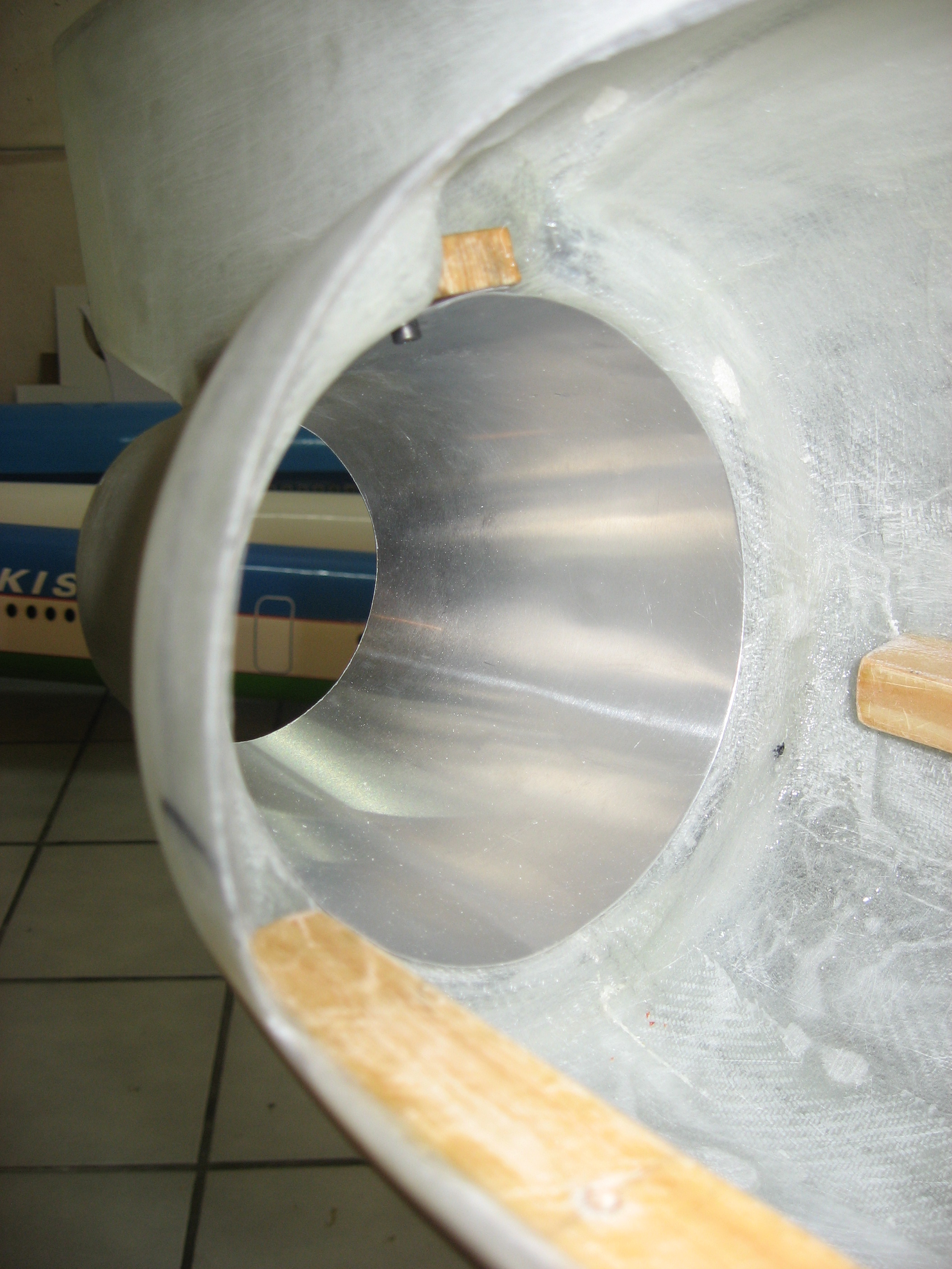
Der Lufteinlass mit 135 mm
Durchmesser wird in der Gondel des Hecktriebwerks verklebt
The 5.3’’ wide airduct is being glued into the tail engine nacelle

Seitenruder
Rudder
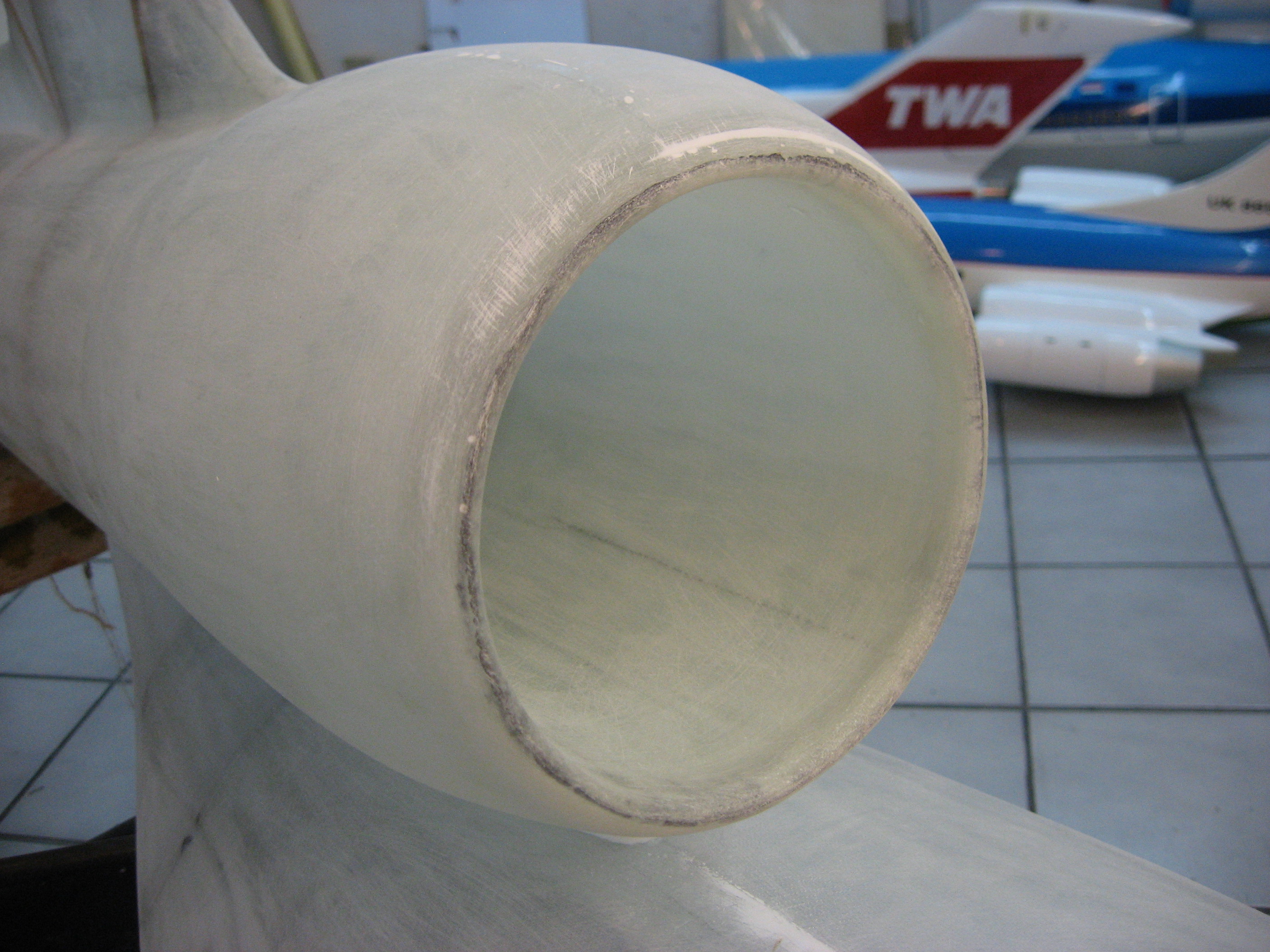
Innenverkleidung als
Wärmeschutz für den Triebwerksauslass
Heat protection for the exhaust cone of the engine nacelle

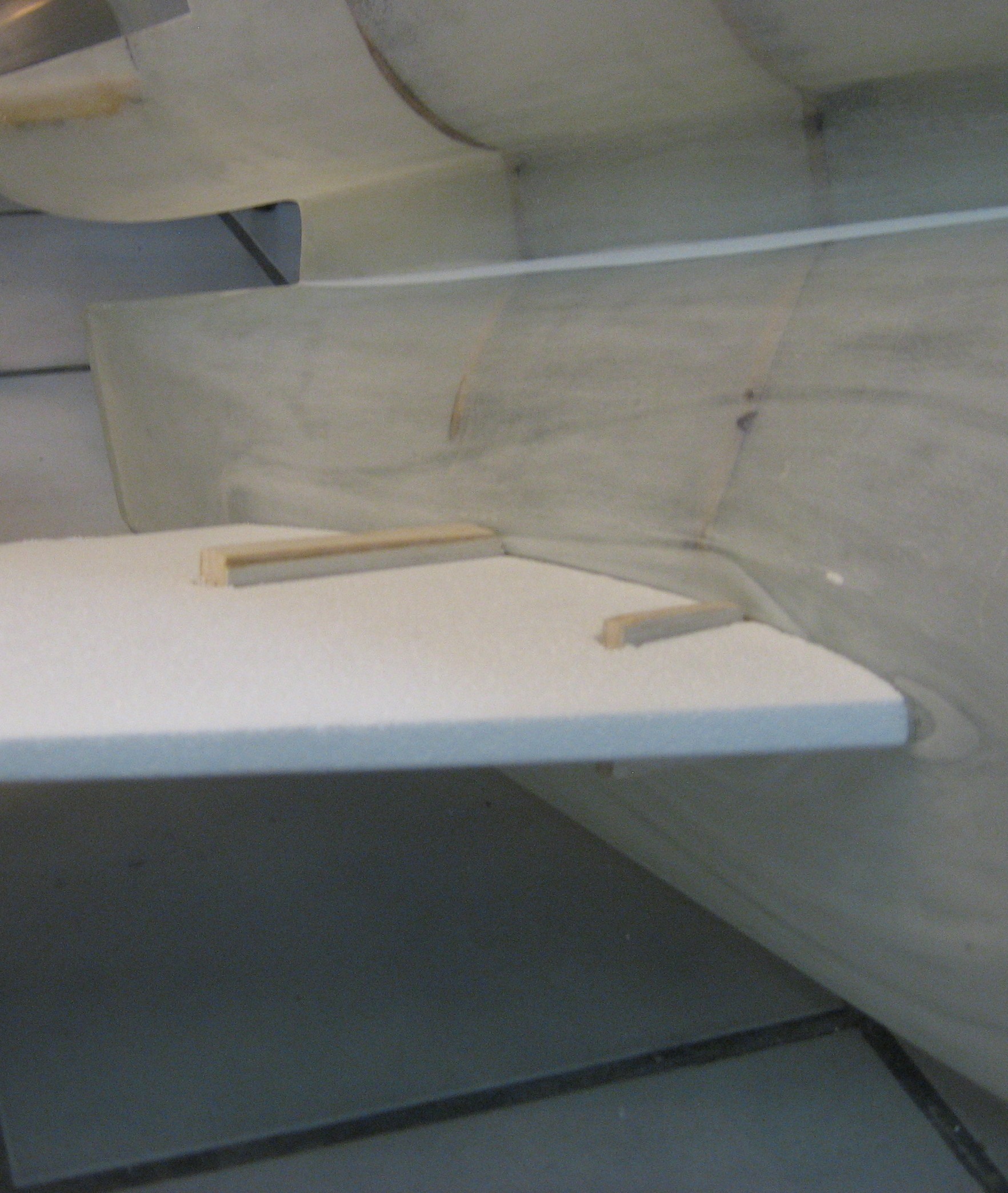
Halterungen für die
Steckungsrohre werden in HLW-Styrokernen verklebt
Mounting for the tubes glued into the stabilizer foam cores
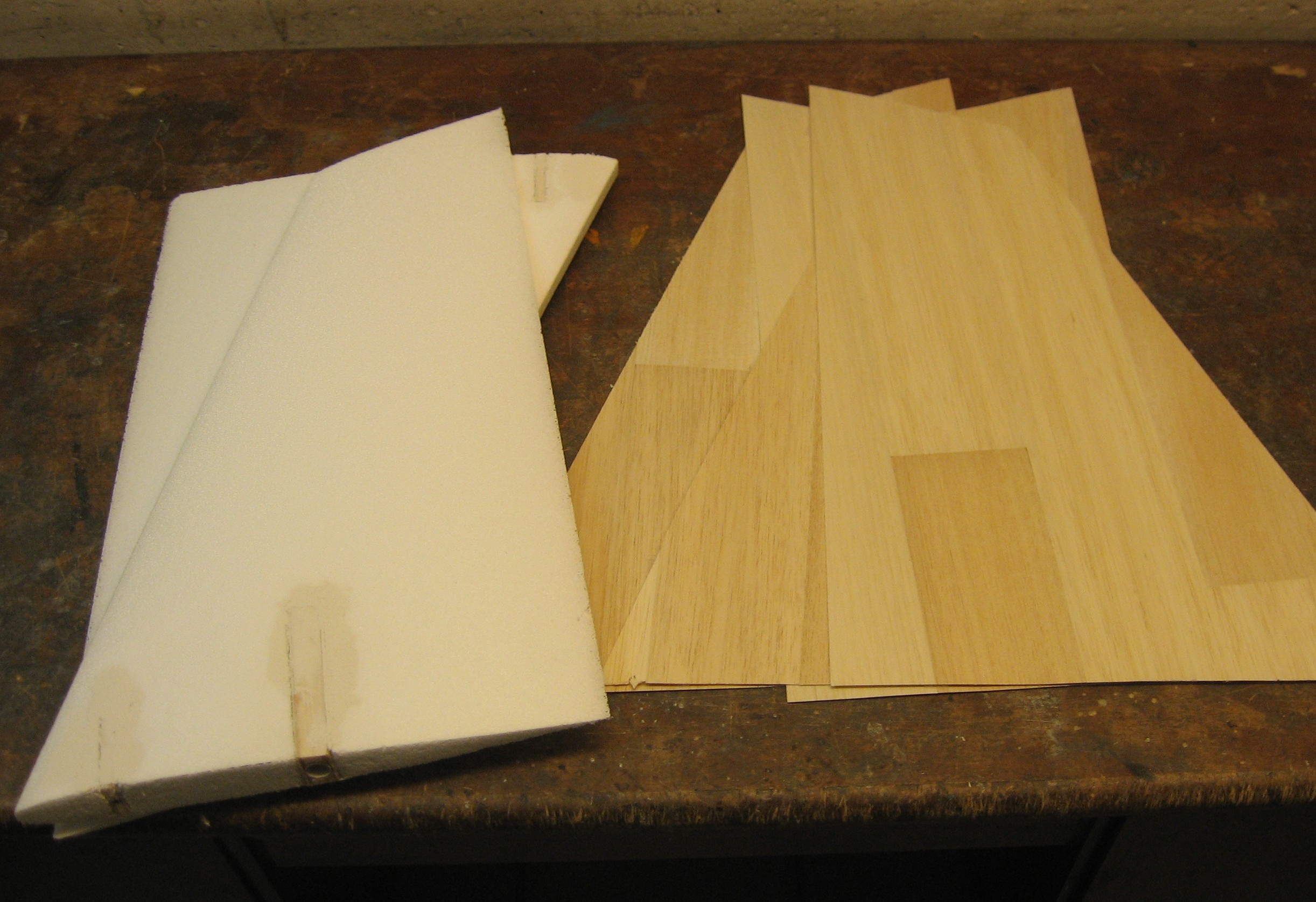
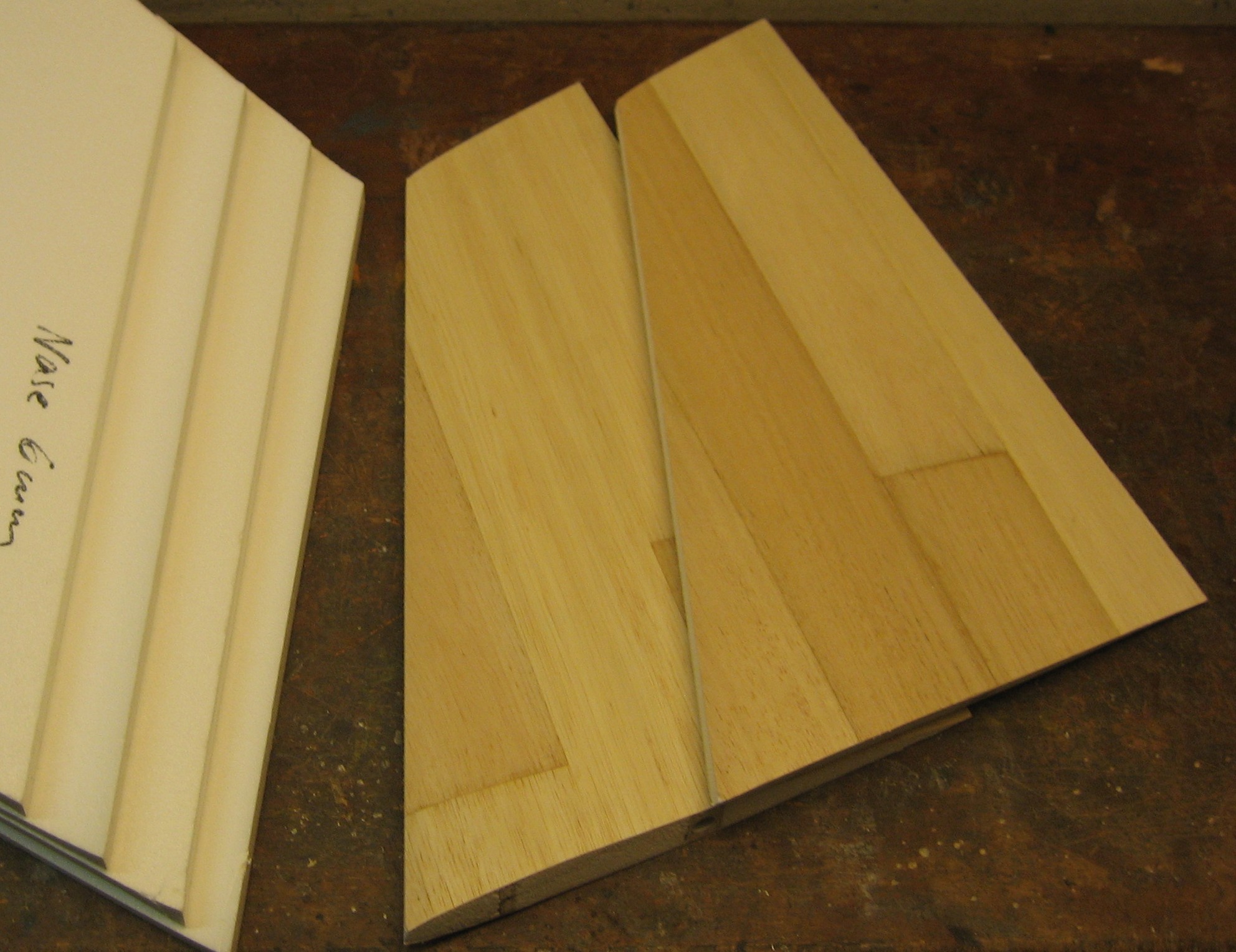
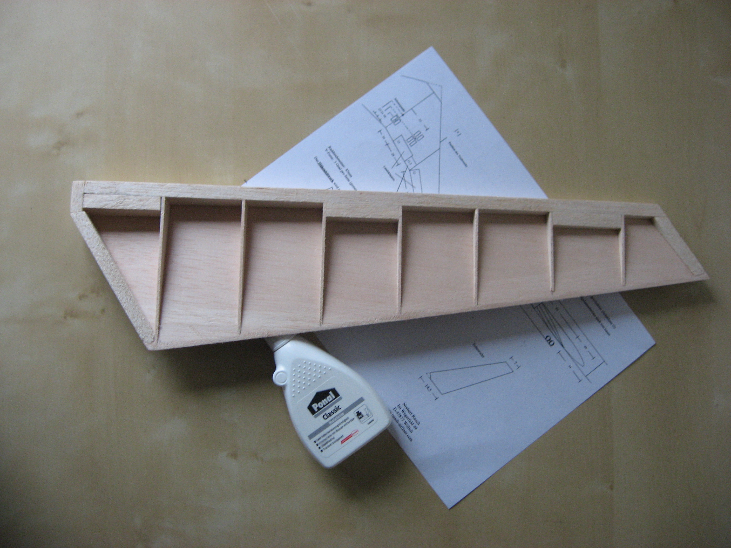
Beplanken der HLW-Kerne
mit 1 mm Balsa
Covering the stabilizer cores with balsa sheeting (1 mm)

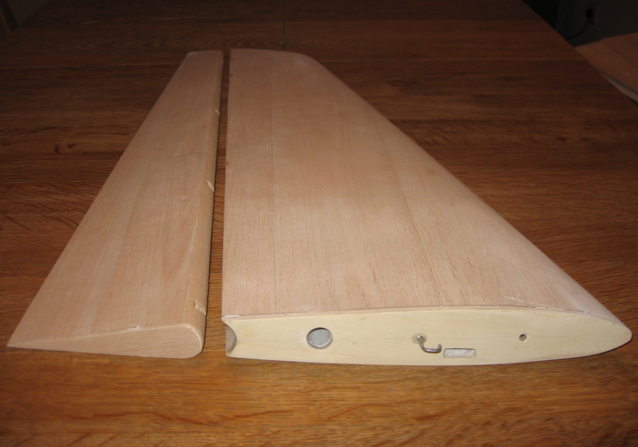
Die Höhenruder sind aus
dem Leitwerk geschnitten
Elevators have been cut out
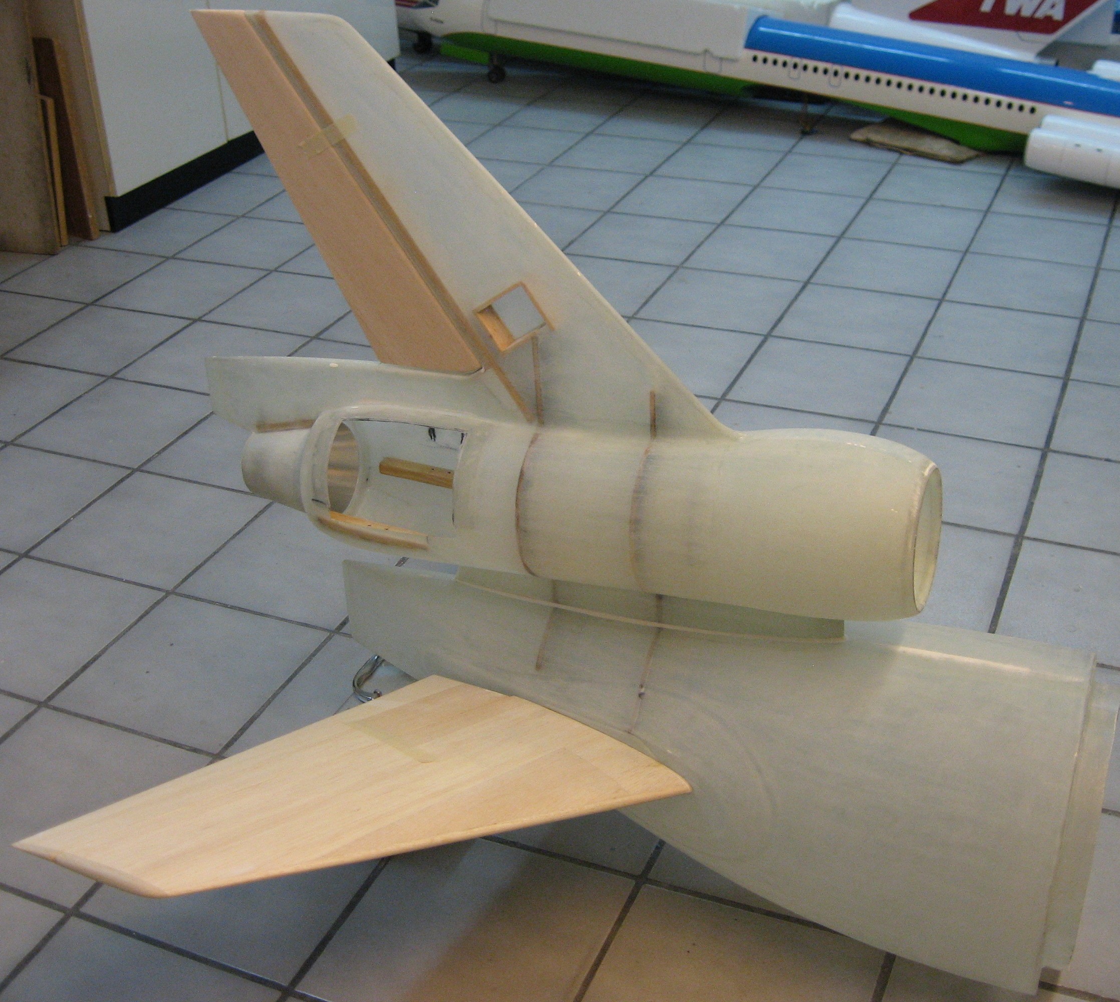
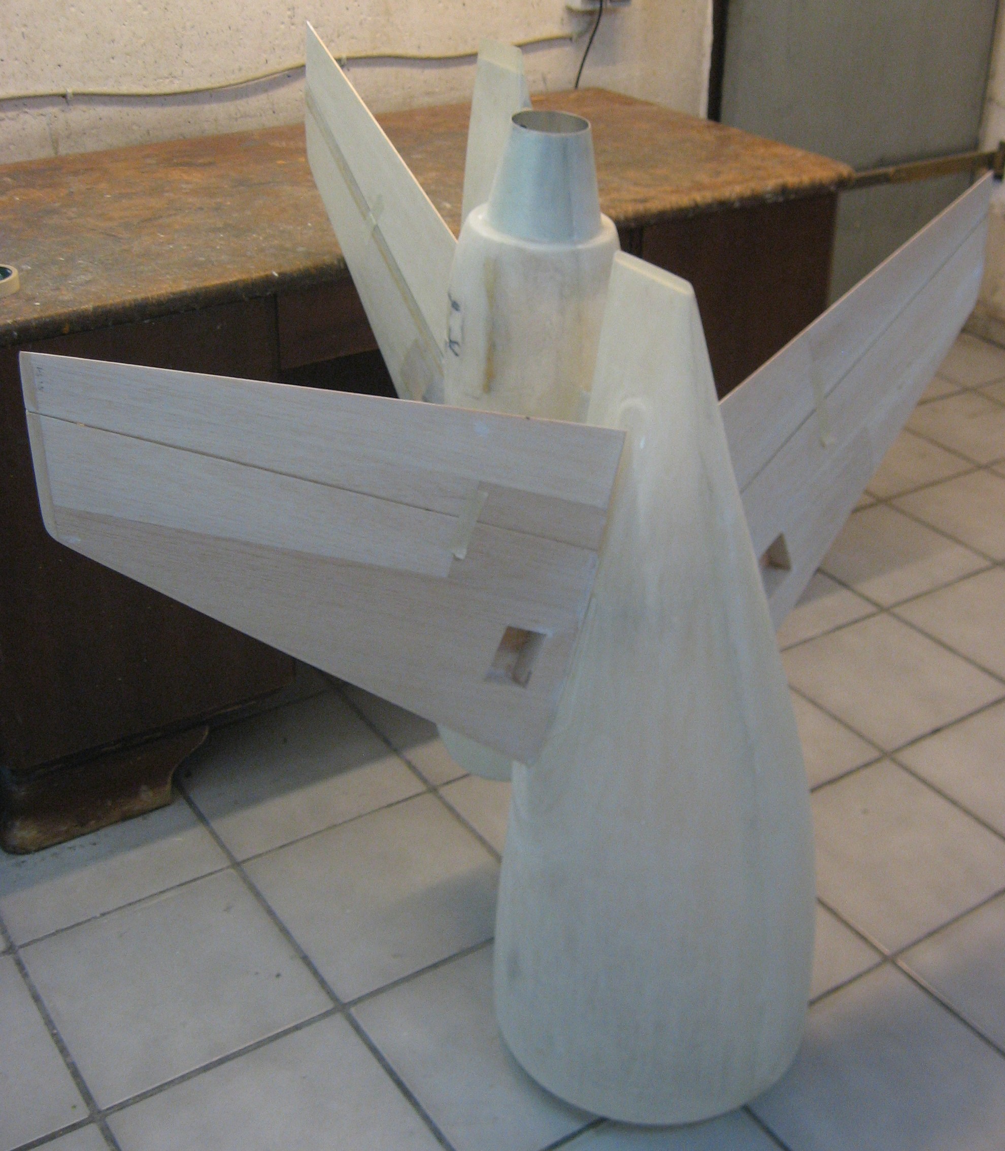
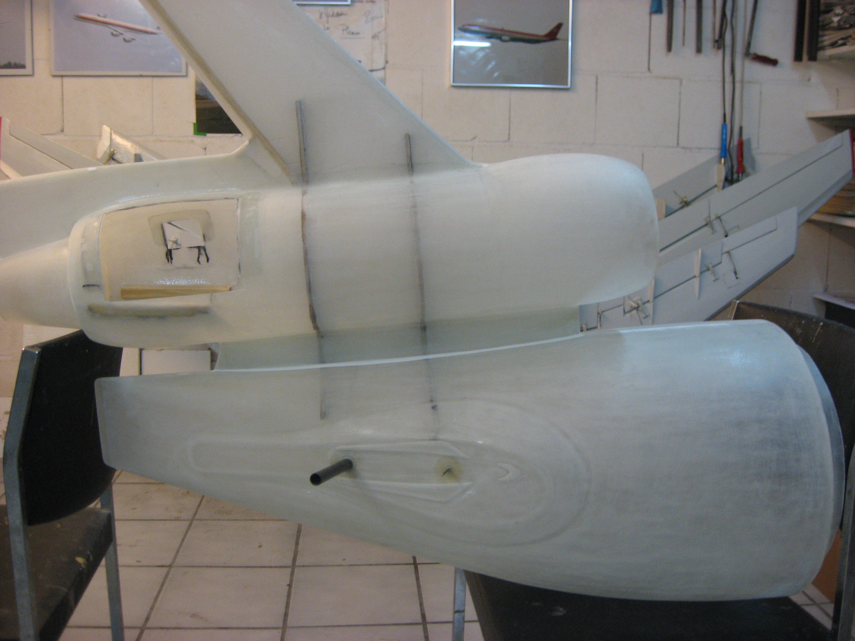
Rumpfheck fertig zur Endmontage, HLW-Spannweite 114 cm
Tail section ready for final assembly, stabilizer span 45’’